Subgroup Collaboration
The CAD for the robot actually involves the entire team. Every subgroup has something to do with the robot, and it's the job of CAD to ensure that all subgroups needs are met or compromised on.
Mechanical / Machining
These guys suffer the burden of being the ones unlucky enough to build our designs.
These guys are the ones who happily build our most amazing designs! It's extremely important to ensure proper communication between both subgroups as the core build of the robot is dependent on the effective communication of the 2 subgroups. Here's a perfect video that explains the relationship between designers and machinists:
To sum up that video, for us what is most important is creating designs that our build team can physically make. Keep designs simple, and easy to assemble. To create a design that adheres to mechanical's build standards, we have to follow a few guidelines:
-
Tolerances must be ≥ 1/8in unless ABSOLUTELY NECESSARY. (Perhaps consider utilizing a factory edge if possible)
-
If the part you are designing has measurements that aren't on a tape measure, the part is too complicated.
-
Consider what parts are better off with machining vs parts that could be better off with more accurate methods like CNC & 3D Printing
-
Ensure any hole sizes are matching the tap sizes on the standardized chart (opens in a new tab).

It's important to keep designs realistic to the build capacity of the team to ensure faster and more efficient use of time during the limited weeks we have to complete a robot. Any delays just hurt the other processes of the robot build.
Electrical
The electrical board is easily the most annoying part of the entire design. Having a student dedicated to just the board is absolutely necessary to keep the sanity of everyone else. That person would act as the representative for electrical to imagine the cable outings and claiming spaces where electrical deems is needed for wires/componenets.

Based on the required sensors/motors the electrical board can easily be changed, causing a lot of time waste. It's important to have a list of what electronics are being used on the robot beforehand to keep the design moving fast.
When designing the electrical board it's important to keep these questions in your head:
Can a wire connector fit in this area?
Will there be any interference with the routing of these wires?
Can the wires bend in a proper angle without creating too much stress on the component?
Is there easy access to the electrical component?
Thinking of everything earlier can save plenty of time like mentioned in the previous doc.
Programming
Probably the most neglected part of the design process... Yeah... we kind of just forgot about programming sometimes. All sensors & cameras are decided by programming and is the job of CAD to get the right angles and placements required for programming's needs.

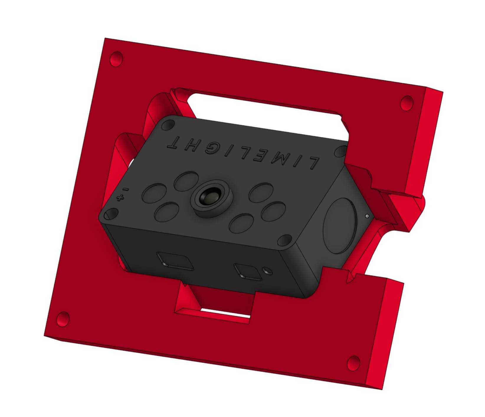
Pro tip: you can constrain sketches to 3d parts like in this case to show the FOV of the camera to help with planning
Right after coming up with the structure of the robot, the next step is to figure out what programming needs and where everything needs to be placed. Our 2024 season left me clueless as to where to place the limelights that we were planning on using, and as a result programming gave me a lot of headaches.
Don't forget to think of openings for cooling fans, accessibility for any wires, and any exhaust cutouts for airflow
P&C
Towards the end of the design process, the fun begins with figuring out the overall color scheme and the sponsor panels. This is my favorite part since this is where we get to make the robot look cool!
Checkout the CAD recaps to see the cool designs!